Credit for this information goes to Markus Ritter owner of a Mariner 36 s/v Sankaty check out his website at http://sankaty.homestead.com

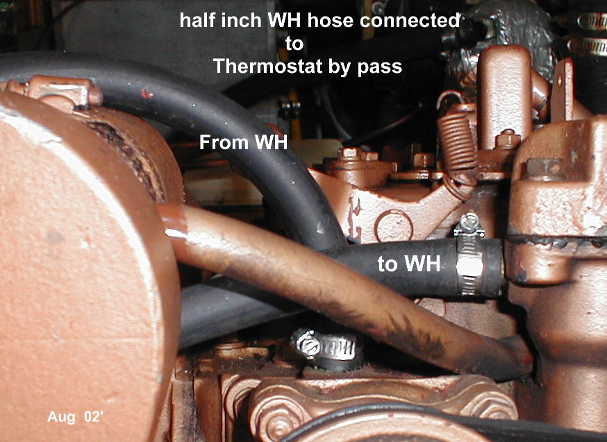
- Original Front view. with five inch long 1/2″ ID Thermostat by pass hose

- Existing barbs are good enough for 1/2 inch ID hose. Original Barbs in place

- I ended up using a 1/2″ hose on the existing barbs. The 1/2 ” hose runs about three feet back to the existing 5/8″ heater hoses. At that point there is a 1/2″ to 5/8″ plastic adaptor that makes the conversion as shown.

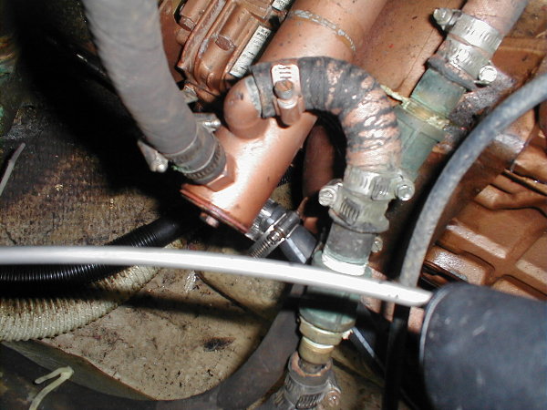
- Plan view w/o brass elbow
I have found some brass 90 deg elbows that may fit into the pipe thread of the engine so that the “From WH” line can stay below the “to WH” line to make it easier to fill the water heater when changing coolant. I may install them next winter, but so far everything is working OK and our continuous speed is 15% faster as we are no longer cooling system limited. Click here for curves showing temperature after one hour runs a various speeds. Check out Racor’s comments on blow by.
Front View
w/o
Brass Elbow

There is a manufacturer that specializes in marine heaters
I ordered their H-406, H-417, and H-407 3/8″ Male Pipe Thread to 5/8″ inch hose adaptors, but I have not installed them yet.
Heater Craft’s, Dan Shull at 208-687-4400.
or e-mail him by clicking here
Westerbeke has the straight adaptor P/N 302391.
I have not been able to get the old barbs out yet. The system is working fine now so I may never add the brass elbows. It is difficult to get the air out of the water heater lines, and I expect that the 90 degree elbow in the WH return line will help that as the fill point at the thermostat will be higher than the return line.
Next time I have to bleed the air out of the coolant system I will temporarily put the coolant recovery reservoir about a foot or two higher than the water heater when I loosen up the hose at the water heater to let the air out.
***************************************************************************
The
Coolant Recovery Reservoir
requires a good pressure cap.
That is, the cap must have two sealing surfaces. One to the outside air at the top of the cap, and the second at the entrance to the engine. When the pressure exceeds 14 psi the fluid flows into the cavity just below the top of the cap and subsequently into the little ¼” tube that is connected to the Recovery Reservoir.
When the coolant in the engine cools it will contract and the air in the tank will go to a much lower pressure. The pressure cap must then allow coolant to flow through a check valve in the center of the cap, essentially sucking coolant out of the recovery reservoir and back into the engine.
So the cap must let coolant out when the pressure is high in the engine and suck it back in when the pressure is low in the engine.
To see an animated diagram of how the pressure cap works.
Do not confuse coolant recovery reservoirs with auxiliary expansion tanks. Below is a little cross section of a radiator pressure cap showing that the seal at the top is critical to being able to draw fluid back into the radiator from the coolant recovery tank.

The expansion tank may not really be required. Consider raising the coolant recovery reservoir about six inches higher than the water heater and filling it with coolant. The coolant will force its way to the heater after an opening is provided at a high point that will let the air out. A petcock at the heater can be left open till the coolant starts to come out of it. This assumes a perfectly good pressure cap that needs very little reverse pressure to let coolant go int
Overheating Causes
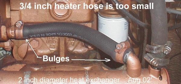
I understand that 7/8 inch exhaust hose is available with wire reinforcement, and hose lengths are available from Westerbeke see parts list manual P/N 200147. page 42
On our diesel Universal marine engine, moving the water heater from the “in series with the heat exchanger position” to the Thermostat by-pass made it possible to go at the boat hull speed continuously..
Above are the steady state temperatures at various speeds before and after the changes. The original red line is with the original 3 GPM Oberdorfer. the blue line after the
6 GPM Sherwood was added. The green line is after the water heater was moved. Westerbeke calls this the “positive flow, hot water heater connection in the thermostat bypass circuit”


Recent Comments